
In-Depth Performance Analysis of 1MIP Versus 2MIP on Single Axis Solar Trackers
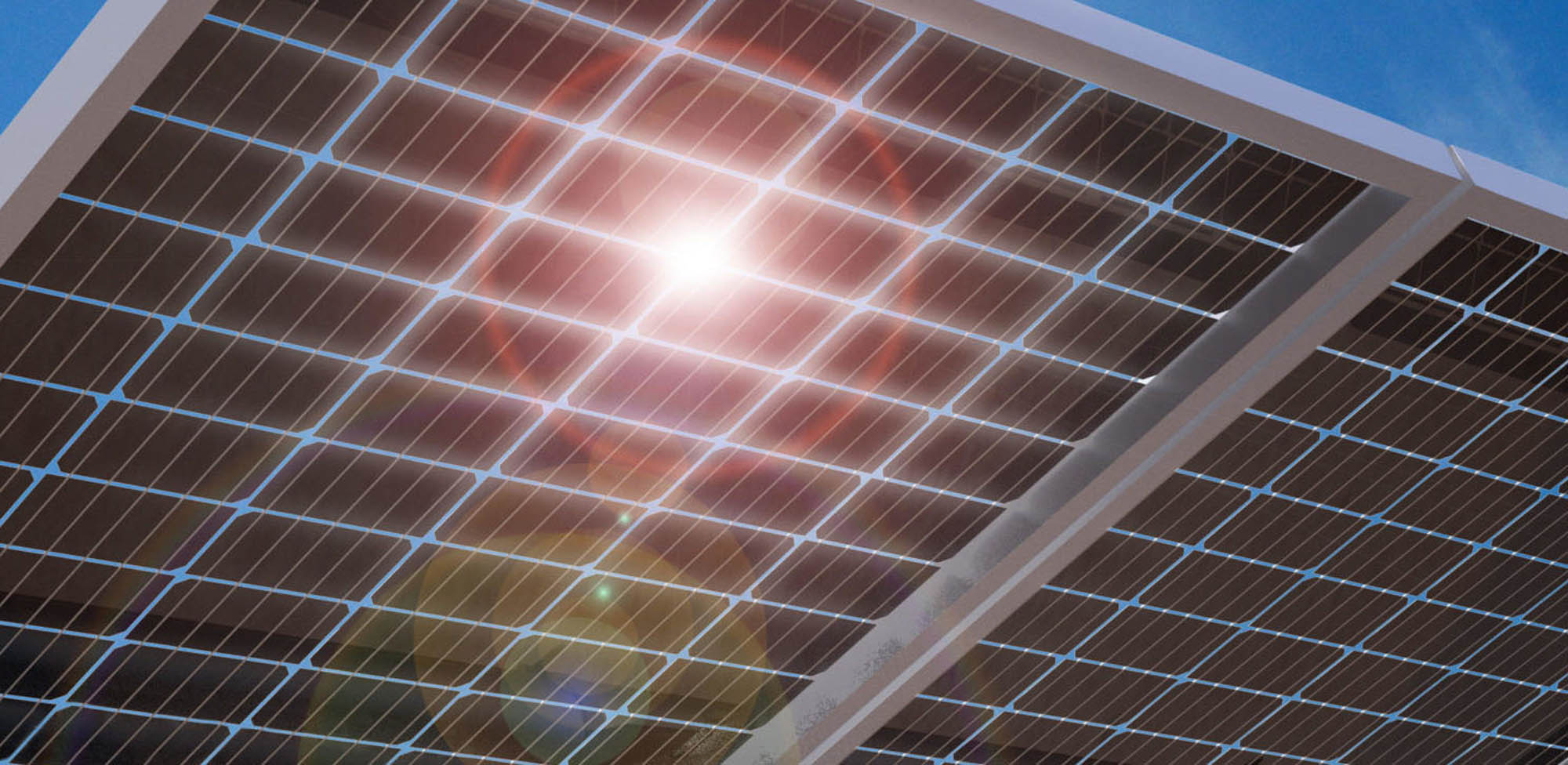
Bifacial modules seem to be all anyone is talking about in the solar industry these days. In true solar coaster fashion, imported bifacial modules were made exempt from the Section 201 tariff, only to have the exemption revoked in October of 2019, then again be put back on the exemption list by the end of 2019—only to be permanently revoked in April of this year. What’s not to investigate in light of such controversy?
What was once a more niche product is undeniably among one of biggest trends. As the technology evolves and becomes more and more mainstream, it makes its way into the wider market where it’s put to the test. What are bifacial modules and why are they gaining popularity?
BIFACIAL MODULES
Bifacial modules are designed to absorb sunlight from both sides, not just one, giving them the ability to capture light that is reflected onto the modules’ backside to increase energy production. Increased energy production is at the top of everyone’s wish list when it comes to owning, financing, or developing a solar project. Higher energy gains mean greater bankability and a more attractive bottom line for all parties. Even a modest increase in energy production can substantiate deploying bifacial modules on a project.
While it’s difficult to pin down the exact boost in energy gain bifacial modules receive on their backside, it is estimated that a 3 to 10 percent increase in energy production is attainable. However, there are some important factors to consider when determining energy yield, such as ground covering, geographic location, and how the module is configured. Such factors could be the difference between a 3 percent boost or a 10 percent boost.
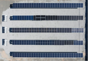
Their popularity brings into question their performance, not only when stacked up against traditional monofacial modules, but quite literally stacked up—in configurations like one module-in-portrait (1MIP), one module mounted vertically, and two-module-in-portrait (2MIP), two modules stacked and mounted vertically. So, now, what configuration is going to optimize the performance of a bifacial module, yielding the highest gain in energy production?
If bifacial modules—which typically yield 3 to 10 percent production gain—are mounted on single axis solar trackers—which typically yield on average 25 percent production gain—will combining the two technologies be a surefire way to maximize an array’s overall energy production? Yes! But gains are only as good as the design of the system.
A recent third-party field test and verified report conducted by CFV Solar Test Laboratory and PV Lighthouse and commissioned by solar tracker pioneer Array Technologies, Inc., dispels the myth that a 2MIP configuration collects more light on the panels’ backside than a 1MIP configuration.
Here’s a deeper look at the performance factors of bifacial modules and why deploying a 1MIP configuration on a single axis solar tracker, specifically the Array Technologies DuraTrackÒ HZ v3, could yield the highest energy gains.
PRIMARY DRIVERS OF BIFACIAL MODULE GAINS
Bifacial module gains are determined by the amount of solar irradiance—the output of light energy—the modules’ backsides receive. Among the primary drivers of these gains are surface albedo, ground coverage ratio, row height and width, and geographic location.
Albedo refers to a surface’s ability to reflect light energy from the sun. If a surface has a high albedo, it means it has a high reflectivity capability. A surface’s albedo is highly dependent on the nature of the surface itself. For example, white or light-colored gravel has a high albedo, reflecting more solar energy than dirt or grass, which has almost no albedo. Green grass absorbs nearly all light. Having ground cover conducive to bifacial modules is important when trying to get the most energy gain from the array’s backside.
Ground coverage ratio (GCR) is the relation of module area to the total land area occupied by a solar array. Shading between tracker rows increases with ground coverage ratio. In other words, the more land area a site’s modules occupy, the more shading that will occur, decreasing the amount of light that reaches the ground within an array. Thus the ability for light to be reflected onto the backsides of the modules is diminished.
Row height in relation to row width or row spacing, called the tracker aspect ratio, along with albedo and GCR determines the amount of solar irradiance that is available for the bifacial module to capture. Sunlight reaches the ground through the space between the tracker rows, then light is reflected back toward the backsides of the modules. If modules are too high or are spaced too far apart, a large amount of reflected light escapes back through the space between the rows and between the ground and the modules, lost to the sky.
While not the largest driver, geographic location can still play a part in the amount of solar irradiance a bifacial module can receive. The amount of solar irradiance available can be limited by an array’s latitude due to how perpendicular the sun is to the array. Regions in higher latitudes receive the least amount of direct sunlight. Moreover, sunlight also has more atmosphere to pass through at higher latitudes, which can scatter the sun’s radiation, making it less concentrated.
The geolocation of a solar array also governs the climate the array will be subject to. It goes without saying that shading is the biggest foe of solar performance, and clear, cloudless days are best for a system to capture the highest amount of energy. Seasonal variations in the sunlight, specifically in winter, increases the farther away from the earth’s equator a solar array is located. The sun is lower in the sky and the shadows are longer. Nearby buildings, trees, and mountains can become impediments, shading an array at certain times of the day during a particular time of year.
Though a solar tracker’s primary function is to follow the sun’s path through the sky throughout the day to constantly adjust the amount of direct sunlight hitting the modules, where a tracker is installed in the world presents an opportunity for further optimization.
THE PITFALLS OF 2MIP CONFIGURATIONS
There are two major structural pitfalls of the 2MIP configuration: potential failures during high wind events due to greater drag and increased array height to account for change in center of rotation.
EXTREME WIND EVENTS
A 2MIP configuration means higher wind loads, and a higher probability for failure. Two modules in portrait essentially creates a bigger “sail” to catch the wind. An argument might be made to strengthen the system with addition support, like longer posts, but this equates to more materials, higher costs, and increased installation times.
Array’s unique wind management system is inherent to the 1MIP configuration. Failure-free wind design and robust architecture are what contribute to the tracker’s high uptime—at 99.996%—and reliability, having proven itself over multiple hurricane seasons. With the exception of the type of module used—bifacial instead of monofacial—nothing about the Array system changes in this instance. No additional hardware or measures are needed to reinforce the system. Tracker manufacturers without a wind mitigation system are doubly at risk when installing bifacial modules in a 2MIP configuration.
The structural strength of the tracker as it exists in its current architecture would be unnecessarily compromised with a 2MIP configuration.
ARRAY HEIGHT
A 2MIP configuration requires the modules to be mounted farther from the ground. The height of the stacked modules changes the center of rotation on the torque tube to give the bottom edge of the module proper clearance as it tracks. As outlined earlier, having modules higher off the ground decreases gain due to the amount of reflected solar energy lost to the sky. Added height, without added row spacing, also increases ground shading, which in turn increases GCR, letting less solar irradiance reach the ground to be reflected.
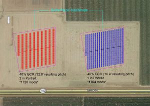
Because of the tracker aspect ratio, a site using a 2MIP configuration would also need to take up more land—which site boundaries may prohibit—to account for wider row spacing in order to achieve the same row height to row width ratio as a 1MIP configuration. To match the tracker aspect ratio of the shortest 1MIP configuration, a 2MIP tracker would need to be built with the torque tube at nearly 3 meters high.
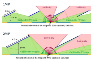
As visualized in the diagrams, there is an 11% increase in light capture with the lower torque tube height of the 1MIP configuration, which does not allow as much reflected light to escape.
Height increases impact installation costs negatively due to deeper foundations, more hardware and structural support to provide stability, and additional installation labor costs with above head-height modules.
A REBUTTAL AGAINST PERCEIVED STRUCTURAL COMPLICATIONS
When analyzing the 1MIP configuration model on an Array tracker, concerns arose about the shading the torque tube would cause. After tests were conducted, the loss of reflected solar irradiance from torque tube shading is very small, as in 0.2%. The torque tubes cast only a soft shadow as irradiance is arriving at the backside of the module from multiple directions, and from both sides of the torque tube.
Array has overcome such a dip in productivity by developing a specific module clamp to use in conjunction with bifacial modules. The “high rise” clamp lifts the module away from the tube, creating more space between the back of the module and the torque tube in an effort to reduce the small area of shading.
To dispel any potential weakness the high rise clamp may possess, Array has engineered the clamp to be able to withstand even more extreme wind events than standard clamps. And while bifacial modules don’t require high rise clamps, customers may choose to deploy them for the small gain the system can capture.
BIFACIAL BANKABILITY
Bifacial technology is continuing to evolve, the cost quickly becoming comparable to that of standard monofacial modules. State-of-the-art tests and simulations like those organized by Array Technologies are integral in analyzing energy yields under different conditions and in different configurations, helping determine ways to improve project profitability.
Optimal energy production is paramount to key players involved in the development of a solar project. The higher a system’s yields, the better the return on investment. The economic viability of a project can depend on a few factors, such as the quality of the product(s) installed, the cost to engineer, supply, and build the site, and the cost to maintain it throughout its lifetime. Accurately estimating these factors for bifacial projects can mean the difference between having a profitable project and not.
Array’s flagship solar tracker already fundamentally achieves 7% lower levelized cost of energy (LCOE)—the cost of generating energy over an array’s lifetime—than competitors, and it boasts one of the highest bankability profiles on the market. At 31% lower lifetime O&M and zero scheduled maintenance, the Array tracker is built to deliver high returns through long-term asset performance.
Over the course of three decades and more than 10 gigawatts of projects, the engineers at Array have proven the 1MIP configuration with a variety of monofacial modules. The system is tried and true, time-tested with proven performance. A project deploying bifacial modules 1MIP would mirror a project deploying monofacial modules 1MIP, therefore upholding Array’s longstanding market reputation.
Using proven, reliable technology means low risk. Considering that the cost of bifacial modules is comparable to monofacial modules and will continue to drop in price as the technology progresses, deploying bifacial modules on an Array tracker only increases energy gains—not tracker material or labor costs and definitely not risks associated with structural complexities of 2MIP configurations. A 1MIP configuration will be more durable over time, as has been proven by Array’s market leadership.
Bifacial modules can amplify the productivity of solar trackers, but twice the number of modules on the racking doesn’t mean twice the energy gains. With double the weight and surface area mounted on a row of foundation posts, the supporting I-beams need to be significantly thicker and longer to account for the added weight of the system, in addition to wind forces that will be acting on the system in the 2MIP configuration. Costs per watt increase with 2MIP, with added hardware and more robust materials, added labor, and slower installation times due to the increased number of components in need of assembly and assembling the system at an above-head height. A 1MIP configuration limits the amount of hardware needed to mount one module, rather than the longer, supportive rails requires for mounting two modules. Moreover, using 1MIP will not require adjustments to the architecture and structure of the foundation or tracker.
CREATING A MORE VALUABLE PROJECT
Rapid adoption of bifacial modules is expected to quadruple in the coming years. Some experts expect bifacial modules will eventually dominate the utility-scale market. The technology is still relatively new, however, and there is no one answer for determining the average gain of bifacial modules. As illustrated, it is highly dependent on a number of factors, and the bifacial module-solar tracker opportunity is complex, though has immense potential.
Could solar trackers and bifacial modules be a match made in heaven? Evidence might suggest so. Afterall, the potential to provide higher energy yields by absorbing energy from both sides of the modules, as opposed to just one, is a major value proposition for project owners and financers. But the true match stems from deploying a configuration conducive to building a more valuable project for the long-term. Contrary to the logic that twice the modules yield twice the energy, extensive testing is conclusive in debunking the myth that a 2MIP configuration is superior to a 1MIP configuration.
Though impacts like the project’s latitude, the ground cover beneath the array, and the weather all influence the amount of reflected sunlight bifacial modules capture, field tests prove that a 1MIP configuration increases energy production, absorbing more solar irradiance that 2MIP would otherwise lose to the sky. Overall lower costs per watt can be achieved using a 1MIP configuration, plus the 1MIP configuration is backed by the failure-free wind design of the Array Technologies tracker. With a 2MIP configuration, project owners and developers are looking at higher material and installation costs as well as higher risks—more parts mean more potential failure points.
For Array Technologies’ field test results, visit https://arraytechinc.com/1mip-vs-2-mip-the-facts-on-bifacial-gain/


