
CAB Wire Management System Considerations
for the Array Technologies Single-Axis Tracker
What is CAB?
The Cambria County Association for the Blind and Handicapped (CAB) produces an above-ground wire management system that can be used in lieu of trenching to carry wires from throughout the field to combiner boxes, inverters, etc. The system is comprised of a steel or copper composite messenger wire (the latter can also be used as EGC or GEC), hangers, brackets, and other fittings supported by piles. The tracker foundation piles are often used to support the CAB system as well. Although, the CAB system can also be supported on its own dedicated piles.
Impact of CAB on Tracker Piles
If supported by the tracker foundation piles, the CAB system will introduce some loads to those piles in addition to the tracker loads. Obviously, dead load (the weight of wires and the CAB system itself) will need to be carried by the foundation piles. In colder climates, ice can form on the wires. The weight of this ice must also be carried by the foundation piles. In most cases, this additional weight is small relative to the loads from the tracker. However, if the soil is loose or weak, this additional load could result in slightly deeper pile embedment.
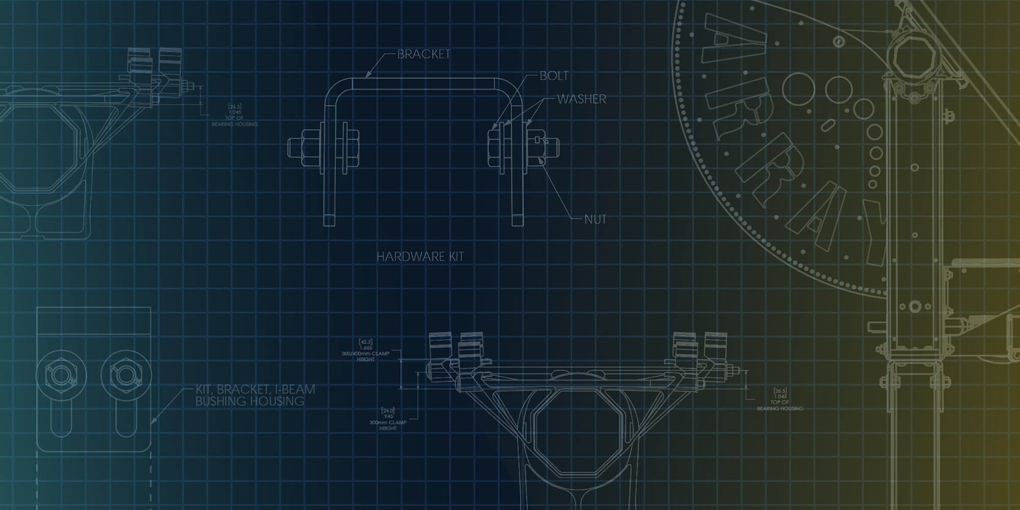
The CAB system can run either north-south (along a tracker row) or east-west (between tracker rows). For north-south runs, the CAB system can be mounted to the tracker pile or to the tracker torque tube. For east-west runs, the CAB system usually runs parallel to the driveline and is mounted to the center structure of the Array tracker. The center structure is fabricated with holes specifically for mounting the CAB system. The L brackets for the CAB system can be mounted either to the lip of the vertical member or to its web.
Load Limits
To avoid overstressing the vertical member of the center structure, there is a load limit placed on the CAB system based on the mounting locations. For brackets mounted to the lip of the center structure, the load limit is 250 lb-ft. For brackets mounted to the web of the center structure, the load limit is 500 lb-ft (if using a 2” wide L bracket.) The units of these load limits (lb-ft) might seem a little strange. That is because the L bracket of the CAB system projects away from the face of the support. The farther it projects, the less weight it can carry. CAB produces L brackets with different project lengths, from 5.5” to 12”. The most common L bracket used for mounting to the lip of the center structure has an 8” project length. This means that the total weight of the CAB system (dead load and ice load combined) can be a maximum of 375 pounds. If mounting the CAB to the web of the center structure with a 12” L bracket, the total weight of the CAB system can be a maximum of 500 lbs.
Determining the dead load of the CAB system is pretty straightforward. Just add up the weight of all the wires being carried. Wire weight is usually given in pounds per foot. Multiply this weight by the spacing between pile supports and you have the dead load acting on a bracket. Determining ice load can be a bit more complicated. But if you want a ballpark estimate of ice load, you can assume it will be about the same as the dead load. As long as the total of the dead load and ice load is less than the limits mentioned above (375 pounds for lip-mounted brackets or 500 pounds for web-mounted brackets), then there should be no issues with using CAB.
Dead-End Piles
The CAB system is a cable structure. That means it is able to carry a significant amount of load over large spans very efficiently simply by placing a slender cable (the messenger wire) in tension. When the messenger wire runs over a support, the tension in the wire on one side of the support is balanced by the tension in the wire on the other side. The support needs to carry only the vertical weight of the CAB system. However, eventually the CAB run must come to an end. The last support at the end of a CAB run does not have balanced tension on both sides. Therefore, the last support at the end of a CAB run must carry a substantial horizontal load in addition to vertical load. This last support in the CAB run is called the Dead-End Support, or Dead-End Pile. The tension in a fully loaded messenger wire can be on the order of 1500 lbs to 2000 lbs. This is comparable to the load on a tracker pile. As a result, it is fair to assume that the dead-end piles of a CAB system will be same size and have the same embedment depth as a tracker foundation pile. Remember that the dead-end pile must be oriented such that the messenger wire is parallel to the web of the pile; that is, the pile must be loaded in its strong direction.
CAB Messenger Wire Installation Sag
As mentioned above, the CAB system is a cable structure with a messenger wire under tension. Cable structures have been around for centuries. But predicting the behavior of a cable structure is not so simple. The tension in the messenger wire of a CAB system is sensitive to the loads on the wire and to the sag in the messenger wire. The sag of the messenger wire is very sensitive to the length of the wire, the distance between supports, elongation or contraction of the wire due to temperature changes, and movement of the supports. But you do not need to worry about the impacts of all these variables on the CAB messenger wire. We here at RPCS perform all the analysis needed. The most important detail when installing a CAB system is providing the right amount of sag in the messenger wire given the span length between supports and the temperature of the messenger wire at the time of installation. When our recommendations are followed, the messenger wire and dead-end pile will satisfy all structural needs of the CAB system.
Meet Mario Colecchia
Senior Structural Engineer
Welcome to RPCS’s Solar Engineering Blog Series: Everything You Wanted To Know About Solar Engineering But Were Afraid To Ask! Over the course of the year, Senior Structural Engineer Mario Colecchia will be providing an in-depth look at popular solar engineering topics while offering unique insights into RPCS’s project design challenges, solutions, and expertise.